Interference Tests
All Tests
PUMA_RF_LA-5.0 Impact of flashlight interference on LA
Description: The purpose of this test is to assess the sensitivity of the LA algorithm to flashlight interference, across a variety of INRs and duty cycles for interference. To create a carefully controlled interference environment, we make use of the IF mini-interference testbed.
Table 4:
| INR (dB) | SINR | Duty cycle (% of time traffic is running) |
|---|---|---|
| -5 | 20 | (10, 20, 40, 50, 60) |
| -3 | 20 | (10, 20, 40, 50, 60) |
| -1 | 20 | (10, 20, 40, 50, 60) |
| 1 | 19 | (10, 20, 40, 50, 60) |
| 3 | 17 | (10, 20, 40, 50, 60) |
| 5 | 15 | (10, 20, 40, 50, 60) |
| 7 | 13 | (10, 20, 40, 50, 60) |
| 9 | 11 | (10, 20, 40, 50, 60) |
| 11 | 9 | (10, 20, 40, 50, 60) |
| 13 | 7 | (10, 20, 40, 50, 60) |
| 15 | 5 | (10, 20, 40, 50, 60) |
| 17 | 3 | (10, 20, 40, 50, 60) |
Test Setup: Dual stack coffin
- DN → CN is Victim Link and IND → INC is Aggressor link.
Procedure:
- Reboot TGs, DNs, and CNs.
- On DN, CN, IND, and INC update
/etc/e2e_config/fw_cfg.jsonto reflect the following:- Disable TPC.
- Init and Config FW on DNs and CNs.
- Associate link IND and INC.
- Program attenuator on the IND → INC path to ensure STF SNR of link is no more than -5 dB.
- Disassociate IND and INC.
- Assign Golay code 1 to DN.
- Assign Golay code 2 to IND and INC.
- Associate link DN and CN.
- Ping DN → CN and CN → DN to validate connectivity.
- Program attenuator on the DN → CN path to ensure STF SNR of link is no more than 20 dB.
- Associate link IND and INC.
- Ping IND → INC and INC → IND to validate connectivity.
- Run iPerf on the DN → CN with the following parameters:
- 2 Gbps of UDP traffic (bi-directional)
- Packet size of 1500 bytes
- Running time: 5 minutes
- Run iPerf with duty cycle picked from (10,20,40,50,60) in turn on the link IND
→ INC with the following parameters:
- Packet size of 500 bytes, 1500 bytes and IMIX
- Running time: 5 minutes Total
- Reduce attenuation on IND → INC path by 2dB and repeat earlier step.
- Continue above two steps for 12 iterations, i.e. for all values shown in Table 4 above.
Pass/Fail Criterion:
- Short term PER for all combinations of {INR, Duty-cycle} on the link is < 1% + 2xTarget_PER for LA.
PUMA_RF_LA-5.1 UDP Throughput with fixed MCS+POWER settings VS TPC+LA enabled
Description: The purpose of this test to ensure that LA's performance is at least as good as Fixed MCS, given the link SNR yields < 0.1% PER for that MCS.
Test Setup: Dual stack coffin, 325m RF link, 200m Link
Procedure:
- Program attenuator with 0 dB attenuation (LA-TB-1 only).
- Reboot the TGs, the DN and the CN.
- For each MCSx in the set {9, 10, 11, 12}, repeat the following tests:
- On both the DN and CN, update
/etc/e2e_config/fw_cfg.jsonto reflect the following:- Fix the MCS to MCSx.
- Disable TPC.
- Associate both DN and CN.
- Program the attenuator to ensure that STF SNR is at least 2dB above the min SNR for MCSx (LA-TB-1 only).
- Ping DN → CN and CN → DN to validate connectivity.
- Run iPerf (on the TG) for 10 mins with the following parameters:
- 2 Gbps of UDP traffic (bi-directional)
- Packet size of 1500 bytes
- Record the throughput on the link in each direction.
- On both the DN and CN, update
/etc/e2e_config/fw_cfg.jsonto reflect the following:- Enable link adaptation on the link with Max MCS = MCSx picked in the earlier step.
- Enable TPC.
- Associate both DN and CN.
- Ping DN → CN and CN → DN to validate connectivity.
- Run iPerf (on the TG) for 10 mins with the following parameters:
- 2 Gbps of UDP traffic (bi-directional)
- Packet size of 500 bytes, 1500 bytes and IMIX
- Record the throughput on the link in each direction.
Pass Criterion:
- The mean UDP throughput with Link Adaptation is within 95% of Fixed MCS performance.
- Long term PER < Target PER throughout the run.
- Short term PER < 1%+Target PER throughout the run.
PUMA_RF_LA-5.2 Adjacent point-to-point links with early weak interference
Description: The purpose of this test is to assess how well Max AGC tracking, CRS, and Golay Code handle early weak interference. Where Golay code assignment is enabled, assign Golay Code {1,1} to one link and Code {2,2} to the other link. Where Golay code assignment is disabled, assign Golay Code {1,1} to both links.
Note that CRS disabled implies a CRS value of 16 in the configuration, whereas max AGC disabled means AGC is left free-running (see preparation section above).
Table 5:
| Case | Golay | Max AGC | CRS |
|---|---|---|---|
| 1 | Enabled | Enabled | Disabled |
| 2 | Enabled | Disabled | Enabled |
| 3 | Disabled | Enabled | Enabled |
| 4 | Enabled | Enabled | Enabled |
Test Setup: Alpha Turn setup
- Links 10-5 (DN1 & DN2), and (CN1 & CN2) 11-9 & 11-8.
- CN1 → DN1 is Aggressor and CN2 → DN2 is Victim link.
Procedure:
- Reboot TGs, DNs, and CNs.
- On both the DNs and CNs, update
/etc/e2e_config/fw_cfg.jsonto reflect the combinations shown in table 4 above. - Init and Config FW on DNs and CNs.
- Associate link DN2 and CN1 and record Tx beam of CN1 to DN2, by parsing the
value of the following field in fw_stats:
- phyPeriodic.txBeamIdx
- Disassociate DN2 and CN1.
- Add +1 microsecond to the transmit time of slots for nodes DN2 and CN2 in the
fw_cfg.jsonfile, as shown below:- "txSlot0End": 87,
- "txSlot0Start": 7,
- "txSlot1End": 182,
- "txSlot1Start": 97,
- "txSlot2End": 197,
- "txSlot2Start": 192,
- Associate link DN2 and CN2.
- Ping DN2 → CN2 and CN2 → DN2 to validate connectivity.
- Associate link DN1 and CN1 with the CN configured to use the Tx beam recorded
in the earlier step, as follows in
fw_cfg.jsonfile:- beamConfig: 0
- txBeamIndex:
<TxBeam> - rxBeamIndex: 0
- Ping DN1 → CN1 and CN1 → DN1 to validate connectivity.
- Run iPerf (on the TG) on the links CN1 → DN1 and CN2 → DN2 with the following
parameters:
- 2 Gbps of UDP traffic (bi-directional)
- Packet size of 1500 bytes
- Running time: 5 minutes
- Record the throughput on link CN2 → DN2.
- Repeat the procedure for each case shown in Table 5.
- Disassociate DN2 → CN2 and DN1 → CN1.
- On both the DNs and CNs, update
/etc/e2e_config/fw_cfg.jsonto reflect the combinations shown in Table 5 above. - Associate link DN2 and CN2.
- Ping DN2 → CN2 and CN2 → DN2 to validate connectivity.
- Associate link DN1 and CN1 with the CN configured to use the Tx beam recorded in the earlier step.
- Ping DN1 → CN1 and CN1 → DN1 to validate connectivity.
- Run iPerf (on the TG) on the links CN1 → DN1 and CN2 → DN2 with the following
parameters:
- 2 Gbps of UDP traffic (bi-directional)
- Packet size of 1500 bytes
- Running time: 5 minutes
- Record the throughput on link CN2 → DN2.
Pass/Fail Criterion:
- Full UDP throughput of 1Gbps is achieved on link CN2 → DN2 with all the cases listed in Table 5.
- LA is able to maintain MCS 9 on CN2 → DN2 for all the cases listed in Table 5.
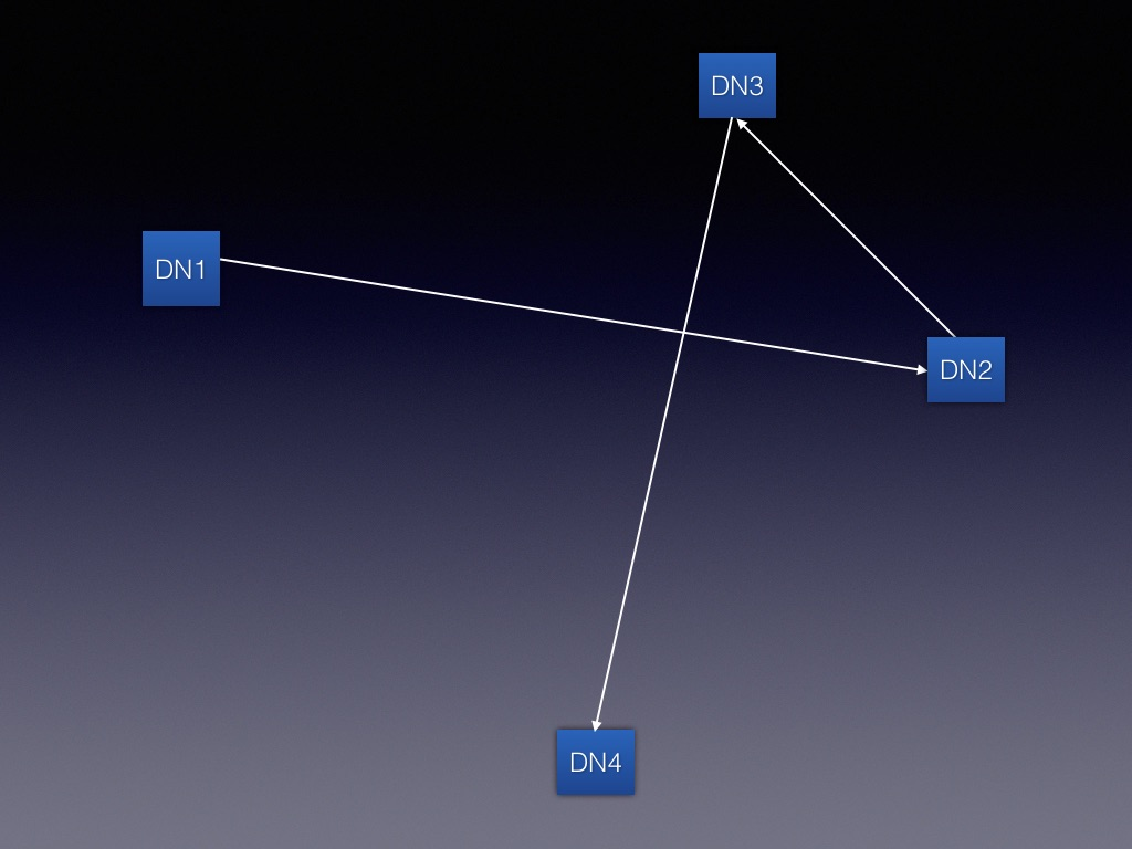
PUMA_RF_LA-5.3 MPK alpha turn with the early weak interference
Description: The purpose of this test is to assess how well Max AGC tracking, CRS Threshold, and Golay codes handle early weak interference. This Alpha turn setup exercises the specific case of a near-far links where the long link transmits at high power and causes interference to the shorter link on the same pole.
Test Setup: Alpha Turn Setup (see below)
Procedure:
- Reboot TGs, DNs, and CNs.
- Init and Config FW on DNs and CNs.
- Bring up the Alpha turn topology using.
- Ping all links to validate connectivity.
- Sample the STF SNR (for ~30 seconds) on each link and verify it is at least 14 dB.
- Run iPerf on each link from link-local to link-local using the following
parameters:
- 2 Gbps of UDP traffic (bi-directional)
- Packet size of 1500 bytes
- Running Time: 3 minutes
- Run iPerf UDP uni-directionally from DN1 → DN4 using the following parameters:
- 2 Gbps
- Packet size of 5784 bytes
- Running Time: 3 minutes
- Run iPerf UDP uni-directionally from DN4 → DN1 using the following parameters:
- 2 Gbps
- Packet size of 1500 bytes
- Running Time: 3 minutes
- Run iPerf UDP bi-directionally between DN1 → DN4 using the following
parameters:
- 2 Gbps
- Packet size of 1500 bytes
- Running Time: 3 minutes
Pass/Fail Criterion:
- Each UDP session in the test achieves full 1Gbps throughput.
- Long term PER < Target PER throughout the run.
- Short term PER < 1%+Target PER throughout the run.
- LA is able to maintain MCS 9 on each link throughout the test.
PUMA_RF_LA-5.4 DN ZIG-ZAG links with nominal 3 hop interference
Description: The purpose of this test is to assess how well TPC and LA adapt to interference from a neighboring high power link that is 3 hops from the victim link.
| Test ID | Link 1 Golay | Link 2 Golay | Link 3 Golay |
|---|---|---|---|
| LA-5.4.1 | {1,1} | {1,1} | {1,1} |
| LA-5.4.2 | {1,1} | {1,1} | {2,2} |
Test Setup: Zig-Zag Setup
Procedure:
- Reboot TGs, DNs, and CNs.
- Init and Config FW on DNs and CNs.
- Configure DN1 to disable TPC, i.e. have it run at full power (=28).
- Configure DNs and CNs to have Golay based on the table above.
- Associate DN2 → CN2, using
r2d2. - Sample STF SNR on the link and record Tx Power on DN2.
- Associate DN1 → CN1, using
r2d2. - Sample STF SNR on the link and record Tx Power on DN2
- Ping DN1 → CN1 and CN1 → DN1 to validate connectivity.
- Ping DN2 → CN2 and CN2 → DN2 to validate connectivity.
- Run uni-directional UDP iPerf from DN1 → CN1 and DN2 → CN2 with the following
parameters:
- 2 Gbps
- Packet size of 1500 bytes
- Running time = 5 minutes.
- Sample STF SNR on the link and record Tx Power on DN2 when iPerf is running in the earlier step.
- Run bi-directional UDP iPerf from DN1 → CN1 and DN2 → CN2 with the following
parameters:
- 2 Gbps
- Packet size of 1500 bytes
- Running time = 5 minutes.
Pass/Fail Criterion:
- Each UDP session in the test achieves full 1Gbps throughput.
- LA is able to maintain MCS 9 on both the links.
- TPC increases Tx Power on DN2 → CN2 to compensate for interference from DN1 → CN1.
PUMA_RF_LA-5.6 Butterfly interference with acute angle CNs
Description: The purpose of this test is to assess how well TPC and LA are able to handle interference between associated DNs, when they are communicating with their respective CNs, i.e. DN → CN, CN → DN. This is achieved by means of a setup crafted with different acute angles between DN-DN and DN-CN links.
Test Setup: Butterfly setup
Procedure:
- Reboot TGs, DNs, and CNs.
- Init and Config FW on DNs and CNs.
- Associate DN1 → DN2, using
r2d2. - Ping DN1 →DN2 and DN2 → DN1 to validate connectivity.
- Associate DN1 → CN1, using
r2d2. - Ping DN1 → CN1 and CN1 → DN1 to validate connectivity.
- Sample STF SNR on the link and record Tx Power on DN2.
- Associate DN2 → CN2, using
r2d2. - Ping DN2 → CN2 and CN2 → DN2 to validate connectivity.
- Sample STF SNR on the link and record Tx Power on DN1.
- Run uni-directional UDP iPerf from CN1→ CN2 and CN2 → CN1 with the following
parameters:
- 2 Gbps
- Packet size of 1500 bytes
- Running time = 5 minutes.
Pass/Fail Criterion:
- Each UDP session in the test achieves full 1Gbps throughput.
- LA is able to maintain MCS 9 on both the links.
- Long term PER < Target PER throughout the run.
- Short term PER < 1%+Target PER throughout the run.
- TPC increases Tx Power to compensate for strong interference between links.
PUMA_RF_LA-5.7 Figure of 8 interference scenarios
Description: The purpose of this test is to assess how well TPC, LA, and AGC work to mitigate interference in a Figure of 8 test setup. We create a few interference-limited topologies to evaluate performance by igniting only a subset of the links to create the U turn, the S turn, and the H configuration. Details are given below. Note, the following the assignment of Golays to each link for all tests:
- Golay 1: Links 0, 1, 3, and 4.
- Golay 2: Links 2, 5 and 6.
This test should also be repeated with the following Golay code assignments:
- Golay 1: Links 0 and 1
- Golay 2: Links 2 and 6
- Golay 3: Links 3 and 4
- Golay 4: Link 5
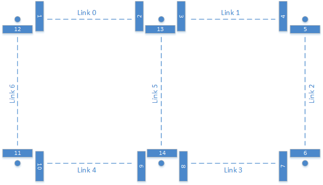
U-Turn:
- Remove links 5 and 6 (U_1).
- Remove links 2 and 5 (U_2).
H-Turn:
- Remove links 2 and 6.
S-Turn:
- Remove links 1 and 4 (S_1).
- Remove links 0 and 3 (S_2).
Table 3:
| Source | Sink | Uni-Directional (each way) | Bi-Directional | Topology Type |
|---|---|---|---|---|
| 11 | 12 | Yes | Yes | U_1 |
| 5 | 6 | Yes | Yes | U_2 |
| 6 | 12 | Yes | Yes | H |
| 5 | 11 | Yes | Yes | H |
| 4 | 10 | Yes | Yes | S_1 |
| 1 | 7 | Yes | Yes | S_2 |
Test Setup: RF Fig of 8
Procedure:
- Reboot TGs, DNs, and CNs.
- Init and Config FW on DNs and CNs.
- Ignite all links using
r2d2or E2E controller. Forr2d2, pay close attention to which nodes are initiator and responder, because this affects how the polarity is configured on the link. By default, the initiator has EVEN polarity. - Ping each wireless hop (using lo interface) and ensure connectivity in each direction.
- Run UDP iPerf from source → sink as shown in Table 3 above with the following
parameters and record throughput:
- 2 Gbps
- Packet size of 1500 bytes
- Running time = 5 minutes.
- Run TCP iPerf from source → sink as shown in Table 3 above with the following
parameters and record throughput:
- 2 Gbps
- Packet size of 1500 bytes
- Running time = 5 minutes.
Pass/Fail Criterion:
- Each UDP session in the test achieves at least 1Gbps throughput.
- Each TCP session in the test achieves at least 1Gbps throughput.
- LA is able to maintain MCS 9 on both the links.
- Long term PER < Target PER throughout the run.
- Short term PER < 1%+Target PER throughout the run.
PUMA_RF_LA-5.8 CN-To-CN interference
Description: This test creates a scenario whereby neighboring CNs 100m apart cause side-lobe interference to one another. It's intended to evaluate whether AGC and CRS features mitigate the impact of interference under these conditions.
Test Setup: CN-TO-CN interference setup (see below)
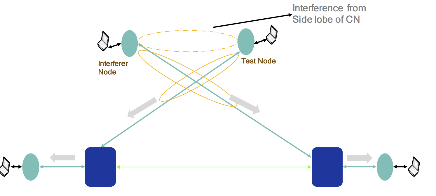
Procedure:
- Reboot TGs, DNs, and CNs.
- Init and Config FW on DNs and CNs.
- Associate DN1 → DN2, using
r2d2. - Ping DN1 →DN2 and DN2 → DN1 to validate connectivity.
- Associate DN1 → CN1, using
r2d2. - Ping DN1 → CN1 and CN1 → DN1 to validate connectivity.
- Associate DN2 → CN2, using
r2d2. - Ping DN2 → CN2 and CN2 → DN2 to validate connectivity.
- Run uni-directional UDP iPerf on CN1→ DN1 and DN2 → CN2 with the following
parameters:
- 2 Gbps
- Packet size of 1500 bytes
- Running time = 5 minutes.
- Record the throughput from DN2 → CN2.
- Run uni-directional UDP iPerf on CN2→ DN2 and DN1 → CN1 with the following
parameters:
- 2 Gbps
- Packet size of 1500 bytes
- Running time = 5 minutes.
- Record the throughput from DN1 → CN1.
Pass/Fail Criterion:
- Each recorded UDP session in the test achieves full 1Gbps throughput.
- LA is able to maintain MCS 9 on both the links.
- Long term PER < Target PER throughout the run.
- Short term PER < 1%+Target PER throughout the run.