System Architecture & Topology
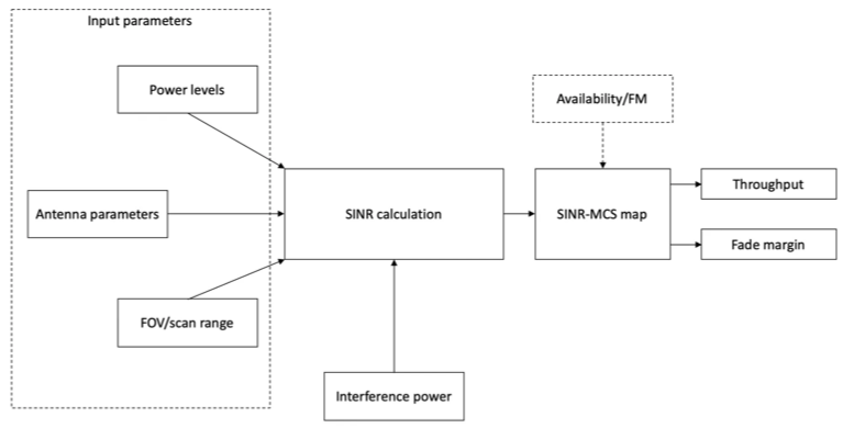
A simplified architecture is assumed for the purpose of modeling various RF parameters as shown in the Figure 1. This is not mean to represent any particular manufacturer’s design but rather a generic communication system architecture sketched as a reference diagram for this document. The diagram here is simplified to represent only a P2P scenario but can easily generalized to a P2MP scenario.

Figure 1: Generlized link budget model
The key blocks in this system include Antenna subsystem, RF front-end and Baseband chipset. The assumed functionalities of these blocks are described below:
- Antenna subsystem: Transmit or receive radio signals in the 60 GHz frequency bands. This could be a single antenna or a group of multi-antenna system abstracted as a single entity for modeling purposes. The overall antenna system is generally assumed to be a directional antenna with antenna patterns being provided as inputs.
- RF front-end: This module interfaces with the antenna subsystem and the Baseband. The key functionality of this module is to up/down-convert the signals to/from higher frequencies (mixing).
- Baseband: As a receiver, Baseband receives down-converted signals from the RF front-end and extracts data (as bits) from these signals. As a transmitter, Baseband provides input signals to the RF front-end for up-conversion to higher frequencies.