Antenna Front End
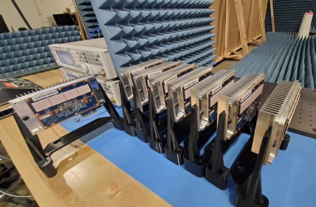
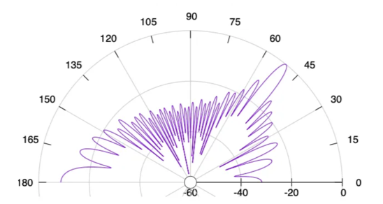
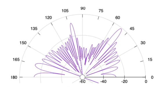
A typical antenna subsystem used in a 60 GHz radio equipment has multiple smaller antennas combining their energies to perform beamforming. A picture of a sample design is show in Figure 2. The ”beam” formed (as shown in Figure 3) can then be steered to a desired direction. Some systems also have the capability to create multiple beams each steered to a different direction, as shown in Figure 4. These are standard features and the TG antenna subsystem is presumed to possess them.

Figure 2: A sample hardware design being calibrated in anechoic chamber

Figure 3: Single beam antenna pattern example

Figure 4: Multi-beam antenna pattern showing an example for 4 simultaneous beams
For the purpose of modeling, the tool requires three categories of input
parameters in order to fully emulate the capabilities described above. Those
files could be added by specifying the file path in the DeviceData struct for
each different hardware.
Single-beam Pattern
A single-beam pattern as shown in Figure 3 is referred to as ”Antenna Pattern File” in the tool. Antenna Pattern File defines the signal loss in the antenna in different angles (similar to Planet’s format as .txt file) with 0th degree being the Boresight gain (dBi). Another input, Horizontal Scan Range (in degrees) should also be provided, representing the horizontal scan range limit of the antenna system.
Common Pattern
Of course, the pattern changes for every steering direction. However, these changes do not cause significant changes in the overall system performance and hence ignored in the tool’s modeling. In other words, the tool takes a common single-beam pattern steered at 0 degrees and rotates (equivalent of steering) to any desired direction.
Antenna Deviation
Generally, DNs are expected to be mounted at relatively higher altitudes than the CNs. Therefore, the DN antennas’ boresight is deviated upwards when looking towards a CN(negative elevation deviation). Consequently, the CN antennas’ boresight is deviated downwards when looking towards a DN (positive elevation deviation). Therefore, the appropriate antenna gains are considered for RSL and SINR calculations, not the full boresight gains.
The result antenna gain with positive or negative elevation deviation should also consider the azimuthal deviation adjustments. In the azimuthal axis, when the two antennas (DN-DN or DN-CN) are not pointing towards each other, the loss in boresight gain is considered. If the antenna pattern in asymetric, we consider the positive deviation for a clockwise deviation (in top view) and negative deviation for an anticlockwise deviation.
Multi-beam Effects
When multiple beams are employed, such as in a P2MP scenario, there is a limit is a 1-3 dB loss across the specified scan range. This loss is generally lower at the angles close to the 0 degree point and can potentially increase at angles away with increasing angle. Therefore a file defining the signal gain of the antenna boresight in different scan angles need to be provided as input, specified as ”Scan Pattern File”
Multi-sector Capability
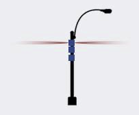
Standard TG devices have the flexibility of creating two simultaneous beams per node. This is shown in Figure 5. These are referred to as Sectors and the input is specified as "Number Sectors Per Node" referring to number of sectors in each node.

Figure 5: Cartoon representing a P2MP system mounted on a light pole
Note that there is a minimum angular limit in degrees between links on different radios on the same site connecting to other nodes. The corresponding input is specified as "Diff Sector Angle Limit".